
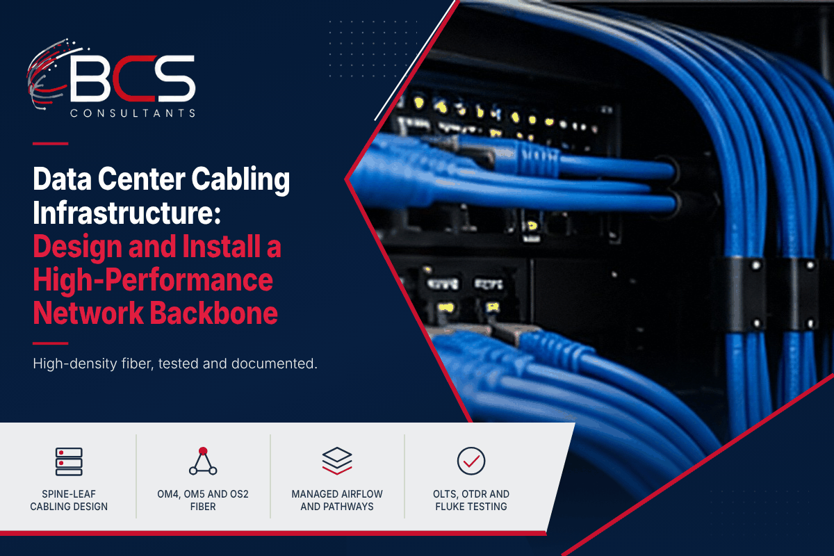
Data center cabling exists at a different scale and with different performance requirements than office structured cabling. The density of connections, the speed requirements, the airflow implications of cable routing, and the cost of downtime if cabling fails all combine to make data center cabling a specialized discipline that requires specific expertise, specific hardware, and a specific approach to design and installation.
BCS Consultants designs and installs data center cabling infrastructure for enterprise data centers and colocation environments, with RCDD-credentialed engineering and Fluke-certified testing at every stage.
Data Center Cabling Architecture: Spine-Leaf and Beyond
Modern enterprise data centers are built on a spine-leaf network topology that has specific cabling implications. In a spine-leaf architecture, every leaf switch (the tier that connects to servers) connects to every spine switch (the core tier) through direct links — creating a consistent, low-latency network fabric where traffic between servers on different leaf switches always crosses the same number of hops (leaf, spine, leaf).
The cabling requirement this creates is significant: in a data center with eight spine switches and twenty-four leaf switches, each leaf switch requires eight uplink connections to the spine switches, totaling one hundred and ninety-two spine-to-leaf links. At high speeds, each of these links may consist of multiple parallel fiber strands. The total fiber count in a medium-sized spine-leaf data center can reach thousands of strands.
Managing this fiber density requires structured fiber cabling systems — pre-terminated fiber trunk cables with MPO/MTP connectors that allow a single cable installation to deploy twelve or twenty-four fiber strands simultaneously, terminating in structured fiber patch panels at each equipment rack. This structured approach to fiber reduces installation time dramatically compared to individual strand-by-strand installation and provides a documented, traceable cabling infrastructure that supports future changes and expansions.
Fiber Types and Speed Requirements for Data Centers
Data center backbone connections operate at speeds ranging from one hundred gigabit to four hundred gigabit and beyond. The fiber type specified must support the required speed at the distances involved.
Multi-mode fiber OM4 supports one hundred gigabit Ethernet at distances up to one hundred meters with standard parallel-optic transceivers and is appropriate for connections between racks and rows within a data center floor. OM5 wideband multi-mode fiber adds support for short-wavelength division multiplexing (SWDM) transceivers, which carry one hundred gigabit over a single duplex fiber pair at extended reach and reduce the number of fiber strands needed per link.
Single-mode OS2 fiber supports any current data center speed at any practical intra-building distance and is specified for applications where the required distance exceeds multi-mode limits, where the future speed requirements are uncertain, or where the incremental cost of single-mode over multi-mode is acceptable given the long infrastructure lifespan.
Pre-Terminated Fiber Trunk Cables
Pre-terminated fiber trunk cables are the backbone of high-density data center fiber installations. A trunk cable contains multiple fiber strands — typically twelve, twenty-four, or forty-eight — terminated at each end with an MPO/MTP connector in a factory-controlled environment. The factory termination quality is consistently higher than field termination quality, and the insertion loss specifications of pre-terminated trunks are precisely documented.
At each rack, MPO cassettes connect the trunk cable to a panel of duplex LC ports — the connector type that standard SFP and QSFP transceivers use. The structured patch panel and cassette system allows any transceiver to connect to any uplink port through two short patch cables: one from the transceiver to the patch panel LC port, and one at the other end. Adds and changes — connecting a new server to a different leaf switch, for example — require only patch cable changes, not new cable installation.
Top-of-Rack Copper Cabling
While data center backbone connections use high-speed fiber, server-to-TOR (top-of-rack) switch connections — the one to two meter runs from server network interface cards to the rack's leaf switch — typically use copper patch cables. Server copper patch cables are short enough that standard Cat6A performance is more than adequate for ten gigabit connections.
For data centers deploying higher-speed copper connections — twenty-five gigabit or forty gigabit to servers using DAC (Direct Attach Copper) cables — the cable type is a specialty product distinct from standard structured cabling. BCS Consultants advises on the appropriate cable type for each tier of the data center network during the design phase.
Cable Management and Airflow
Data center cable management has a direct impact on equipment cooling. Cables that block airflow through equipment bays reduce the efficiency of the cold-aisle/hot-aisle cooling architecture, raising equipment operating temperatures and potentially causing performance throttling or hardware failure.
BCS Consultants designs data center cable management with airflow as a primary consideration. Overhead cable trays route cables above the racks without crossing into the cold or hot aisles at floor level. Horizontal cable managers in each rack route patch cables to the sides of the rack through managed paths that do not obstruct front-panel airflow. Blanking panels fill empty rack units to prevent recirculation of hot air.
Testing and Certification for Data Center Cabling
Every fiber run in a BCS Consultants data center installation is tested with an optical loss test set (OLTS) that measures end-to-end insertion loss, and with OTDR (optical time-domain reflectometer) equipment that characterizes each connection and splice along the path, identifying any faults or high-loss events. Test results are compared to the performance specifications for the cable type and the manufacturer's warranty requirements.
Structured copper cabling in data center environments is tested with a Fluke DSX analyzer to the same TIA-568 standards applied to office installations. The certification report for the complete data center cabling installation documents every tested run and is delivered as part of the project closeout documentation.
Planning for Growth and Change in the Data Hall
A cabling plant is built once but changed for years, so the design should leave room to grow. BCS Consultants reserves spare pathway capacity in trays and ladder racks, plans patching fields with room for additional cassettes, and applies a consistent labeling scheme aligned with ANSI/TIA-606 so that every cable can be traced without guesswork. Fiber polarity is planned end to end and documented, because a mismatch between MPO polarity methods is a common cause of links that will not come up.
Power, Cooling, and Physical Protection Around the Cabling
Cabling does not exist apart from the rest of the facility. Cable trays must be coordinated with power distribution and cooling so that they do not block airflow or violate separation requirements between power and data pathways. Fire-rated pathways and appropriate cable jackets for plenum or riser spaces are selected according to the building and local code, and overhead trays should be supported for the full weight of installed cabling.
Working with the Data Center Operations Team
Installation in an operating data center depends on communication. Work is scheduled in maintenance windows, change requests are approved before any rack is touched, and technicians follow access procedures. BCS Consultants agrees on the sequence of work, the people who must be notified, and the rollback plan before the first cable is pulled, so that cabling projects remain predictable and safe for the live environment.
Frequently Asked Questions
What is the difference between a data center and a telecommunications room?
A telecommunications room (or IDF/MDF) primarily contains structured cabling equipment — patch panels, fiber termination, and network switches serving an office floor or building zone. A data center contains servers, storage, and compute infrastructure with more demanding power, cooling, and redundancy requirements. Data center cabling design must account for these operational demands in ways that standard office cabling design does not.
How does BCS Consultants manage data center cabling installation in a live data center?
Installing cabling in a live data center requires careful management of work zones, strict cable management protocols to prevent accidental disconnection of active equipment, and coordination with the data center operations team on any planned outages for specific rack work. BCS Consultants follows a structured change management process for all live data center work.
What documentation does BCS Consultants provide for data center cabling projects?
BCS Consultants delivers a complete data center cabling documentation package including rack elevation drawings, fiber span documentation, patch panel schedules, OLTS and OTDR test reports for all fiber runs, and Fluke DSX test reports for all copper runs. This documentation is provided in both printed and electronic format.
Should a data center use fiber or copper between racks?
Fiber is typically used for backbone and inter-rack links because it supports high speeds over longer distances, while copper is common for very short connections within a rack. The right choice depends on speed, distance, power consumption, and cost. A design review that compares the options for each network tier avoids paying for performance that is not needed or running out of capacity too soon.
Ready to get started? Request a data center cabling consultation from BCS Consultants · bcsconsultants.com/contact/contact-us/