
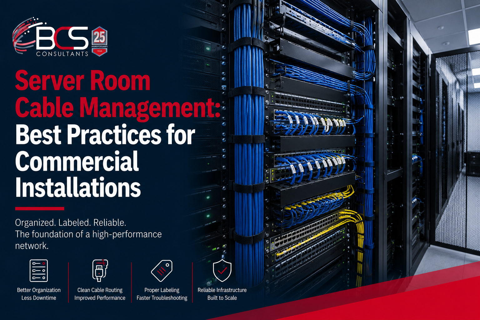
Walk into a well-managed server room or telecommunications closet and the difference is immediately apparent. Cables are routed cleanly from patch panel to equipment, labeled at both ends, organized in horizontal and vertical cable managers, and color-coded by purpose. Every connection is traceable in seconds. Changes can be made without disrupting adjacent connections. The room looks as though someone thought carefully about it before a single cable was run.
Now walk into a poorly managed one. A tangle of cables with unknown paths and uncertain terminations, patch panels where nobody is sure which port connects to which outlet, equipment stacked in whatever space was available, and cables that you cannot move without worrying about what else you might disconnect.
The difference between these two environments is not accidental. Good server room cable management is the result of deliberate planning and disciplined execution from the start of the installation. This guide explains the practices that BCS Consultant applies to every telecommunications room and data center installation.
Plan the Rack Layout Before Touching Any Hardware
The most important server room cable management practice happens before any hardware arrives on site: designing the rack layout. A rack elevation drawing — a diagram that shows exactly which piece of equipment occupies which rack unit in each rack, from top to bottom — is the foundation of an organized installation.
The rack elevation design addresses equipment weight distribution, with heavier equipment like UPS units and blade chassis positioned at the bottom of racks where the center of gravity is lower. It addresses airflow, with all equipment oriented consistently so that cool air intake faces the cold aisle and hot air exhaust faces the hot aisle. It addresses cable routing, with equipment positioned to minimize cable span between connected devices. And it reserves space for future growth — empty rack units and cable management capacity that allow the room to expand without a complete reorganization.
Attempting to design the layout after equipment has been installed is far more difficult and typically results in compromises that create problems for years.
Horizontal and Vertical Cable Managers
Cable management panels are the physical infrastructure that keeps patch cables organized within and between racks. Horizontal cable managers mount between patch panels and the switches or servers they connect to, providing finger ducts through which cables are routed to the left and right sides of the rack before exiting. Vertical cable managers run along the sides of the rack, routing cables between horizontal managers and to the top or bottom of the rack.
The function of cable managers is not cosmetic — cables that are not managed create airflow blockages that reduce cooling efficiency, apply mechanical stress to connector terminations over time, and make it impossible to remove or replace a single cable without disturbing its neighbors. Properly managed cables are accessible individually and can be traced, replaced, or rerouted without disrupting adjacent connections.
Patch Cable Length Discipline
One of the most immediately visible indicators of a well-managed installation versus a haphazard one is patch cable length. Using cables that are significantly longer than required for the specific connection creates coils and bundles that consume cable management capacity, restrict airflow through equipment bays, and make the interior of the rack visually chaotic.
The correct approach is to use cables of the appropriate length for each specific connection — measuring the route from source to destination through the cable managers, not the straight-line distance, and selecting or cutting cables to that length. Patch cable assortments in multiple lengths, or custom-cut patch cables for large installations, allow each connection to be made with the appropriate cable without excess.
Color coding patch cables by function or VLAN — green for user ports, blue for management, yellow for voice, red for security cameras — provides immediate visual identification of cable purpose without requiring label reading.
Labeling: Every Cable, Every End
Labeling is the aspect of cable management most often shortcut and most bitterly regretted afterward. Every cable in a telecommunications room should be labeled at both ends with a unique identifier that corresponds to the documentation — the as-built drawings, patch panel schedule, and test reports.
Labels should be printed, not handwritten. Thermal-printed cable labels on wrap-around label stock are durable, readable, and resistant to the heat and humidity that telecommunications rooms accumulate over years of operation. Labels applied at the time of installation, while the cable path is known, take seconds each. Labels applied later — or not applied at all — result in hours of tracing and testing when someone needs to understand the system months or years later.
Patch panels should be labeled at every port with the outlet number or device it connects to. Racks should be labeled with a rack identifier that appears on as-built drawings. Every piece of equipment should be labeled with a hostname or asset tag.
Power and Data Cable Separation
Power cables and data cables should be routed on opposite sides of the rack wherever possible. Power cables generate electromagnetic interference that can degrade the performance of data cables running in close parallel over extended distances — while the effect is small for modern Cat6A cable with proper shielding, it is best practice to maintain separation, and it makes the installation cleaner and more traceable.
In raised floor data centers, power and data pathways are typically designed separately from the beginning. In standard telecommunications rooms with wall-mounted cable management, the convention is typically to route power cables on the left side of the rack and data cables on the right, or vice versa — consistently, throughout the entire room.
Documentation That Travels with the Room
A telecommunications room installation is not complete without documentation. BCS delivers every project with a complete documentation package: rack elevation diagrams showing equipment layout, a patch panel schedule listing every port and its corresponding outlet or device, as-built floor plans showing cable pathway routes, and Fluke DSX cable test reports for every structured cabling run in the system.
This documentation is delivered in both printed and electronic formats. The printed binder lives in the room. The electronic files are provided to the client's IT team for inclusion in their systems documentation.
Good documentation transforms the room from a black box into a manageable system. It enables new IT staff to understand the installation without calling the original installer. It enables BCS service technicians to work efficiently in the room years after the original installation. It enables future capacity planning without requiring a physical audit of the existing infrastructure.
Frequently Asked Questions
Can BCS clean up and reorganize an existing disorganized server room?
Yes. BCS Consultants performs telecommunications room re-organization projects that involve documenting existing connections, designing the reorganized layout, carefully re-routing cables and equipment, re-labeling everything, and delivering updated documentation. This work is phased to minimize network disruption and is typically performed during evening or weekend maintenance windows.
What is the difference between a 2-post and 4-post rack?
A 2-post open frame rack is appropriate for patch panels, cable management, and lighter equipment. A 4-post rack provides structural support at all four corners and is required for heavier equipment such as servers, storage arrays, and UPS units. BCS specifies the appropriate rack type for the equipment in each rack position.
How often should server room cable management be audited?
A cable management audit is recommended whenever significant infrastructure changes occur — major hardware additions, network redesigns, or decommissioning of equipment. For rooms with active ongoing adds and changes, an annual review helps prevent the gradual deterioration of organization that accumulates from many small individual changes.